
Now, we are picking the first topic in the CCNA blueprint provided by Cisco as my first topic of discussion. Mind you, this is not a tutorial ( … go to Jeremy IT Lab for that). We are going to be using a university as a case study to show how these devices play a role in their environment. For random reasons, we will be using a popular university in United States of America as a case study. “The University of Washington (UW)“, established in 1861, is among the oldest universities on the U.S. West Coast. Its main campus in Seattle covers 700 acres, complemented by satellite campuses in Tacoma and Bothell, and includes more than 500 buildings. As of fall 2024, UW has an enrollment of about 51,719 students – 35,397 undergraduates and 16,322 postgraduates. With a workforce of over 34,600 across its campuses and health system, it stands as one of the largest institutions in the region. For simplicity’s sake, we will assume that they own all of their networking equipment, they don’t use “other people’s datacenter” (i.e., cloud … do you feel the sarcasm here … just kidding).
Pretend for a few minutes you are a network engineer working in this environment, you need devices and systems that will carry internet connectivity across the Seattle campus’s 700 acres, connect the branch campuses, network 500 buildings, provision services such as email, Wi-Fi in addition to making sure that the network is stable and available for educational content delivery to over 100 thousand people !!! Daily !!!
We will be discussing the devices that makes these possible but first, we need to define some basic technical networking terms.
What is a Network?
Every time you want to use Airdrop and Bluetooth on your phones, when those two devices’ pair, they form a network. Also, let’s assume, you use any type of computer cable to connect just two computers, that, in is basic form is a network.
Borrowing a few words from the networking gurus in Cisco,
1.1 Explain the role and function of network components
1.1.a Routers:
This is the networking device that inter-connects different networks and direct traffic to predefined or configured paths, thus deterministically directing data traffic between these networks.
Juniper website defines it comprehensively thus;
“Routers allow devices to connect and share data over the Internet or an intranet. A router is a gateway that passes data between one or more local area networks (LANs). Routers use the Internet Protocol (IP) to send IP packets containing data and IP addresses of sending and destination devices located on separate local area networks. Routers reside between these LANs where the sending and receiving devices are connected. Devices may be connected over multiple router “hops” or may reside on separate LANs directly connected to the same router.
Once an IP packet from a sending device reaches a router, the router identifies the packet’s destination and calculates the best way to forward it there. The router maintains a set of route-forwarding tables, which are rules that identify how to forward data to reach the destination device’s LAN. A router will determine the best router interface (or next hop) to send the packet closer to the destination device’s LAN. Once a device sends an IP packet, routers determine that packet’s best route over the Internet or intranet to reach its destination most efficiently and in accordance with quality-of-service agreements.”
1.1.b Layer 2 and Layer 3 Switches:
Before distinguishing between Layer 2 and Layer 3 switches, it is important to remember that a switch is a networking device that connects hosts within the same Local Area Network (LAN)—this is the fundamental role of a Layer 2 switch. A Layer 3 switch, on the other hand, adds routing functionality, allowing it to manage traffic not only within the LAN but also between different networks and Virtual Local Area Networks (VLANs), similar to the way a router operates. In simple terms, a Layer 3 switch combines the features of both a switch and a router in a single box and can be configured to perform both roles accordingly.
1.1.c Next-generation firewalls (NGFW) and Intrusion Prevention System (IPS):
A next-generation firewall is an advanced security device that goes beyond traditional firewalls. In addition to filtering traffic based on ports and IP addresses, NGFWs can inspect traffic at the application level, detect and block malware, enforce user-based policies, and integrate with threat intelligence. They combine firewall, intrusion prevention, and sometimes even VPN and antivirus features into one system.
IPS is a security tool designed to monitor network traffic programmatically actively for suspicious activities or known attack patterns. Unlike intrusion detection systems (IDS), which only alert administrators, an IPS can be programmed or is programmed to automatically act such as blocking malicious traffic, resetting connections, or dropping harmful packets to stop threats in real time.
1.1.d Access points:
An access point is a networking device that allows wireless devices (like laptops, phones, and IoT devices) to connect to a wired LAN. It acts as a bridge between the wireless network and the wired infrastructure, extending network coverage and enabling mobility. This is the connection you find in public places such as coffee shops, airports, schools etc.
1.1.e Controllers (Cisco DNA Center and WLC)
Cisco DNA Center: A centralized network management and automation platform. It provides end-to-end visibility, policy-based configuration, AI-driven analytics, and automation across wired and wireless networks. It simplifies management by using intent-based networking, where administrators define what they want the network to do, and the system implements it.
Wireless LAN Controller (WLC): A dedicated device or software that manages multiple wireless access points in an enterprise network. It centralizes tasks such as configuration, security, firmware updates, and load balancing. This ensures consistent policies, seamless roaming, and efficient use of wireless resources.
1.1.f Endpoints:
Endpoints are devices that connect to and use a network’s resources. They include user devices such as desktops, laptops, smartphones, and tablets, as well as IoT devices, printers, and servers.
1.1.g Servers:
Servers are powerful computers or virtual machines that provide shared resources, services, or applications to other devices (clients) on a network. They can have websites, manage databases, run applications, store files, handle email, or security services for users and the network alike.
1.1.h PoE:
Power Over Ethernet (PoE) is a technology that allows network cables to carry both data and electrical power to devices. This eliminates the need for separate power adapters. Common PoE-enabled devices include IP phones, wireless access points, and security cameras. It simplifies installation, reduces cabling costs, and provides centralized power management.
Our Network Diagram (Fake Network Diagram)
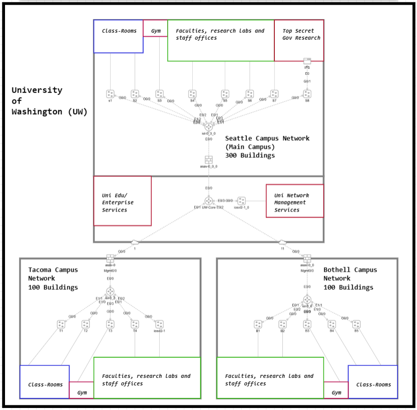
Let us design a felicitous network diagram based on the information available about the University of Washington from Wikipedia. In networking, this kind of setup is referred to as a campus network—a standard enterprise architecture that is customized to fit the unique requirements of each organization. This is why the saying often applies in networking: “no two networks are ever the same.”
The university’s main location is in Seattle, which serves as the central hub of operations. In addition, there are branch campuses located in Tacoma and Bothell, all of which must be seamlessly interconnected to support collaboration and resource sharing.
The scale of the university is significant, with over 500 buildings distributed across its campuses. As of Fall 2024, the institution supports a student population of more than 51,700 and a workforce exceeding 34,600 staff across both academic and health system operations.
For the purpose of this design, we will assume that the university owns and manages all of its networking equipment internally, without reliance on external cloud services or third-party datacenters. This approach highlights the need for a robust, secure, and self-sufficient campus network infrastructure capable of supporting such a large academic and research community.
Routers – The Campus Connectors
Routers are the traffic orchestrators of the UW network. At the Seattle main campus, a core router connects to the branch campuses in Tacoma and Bothell, making sure data travels deterministically between them. Without this router, each campus would be cut off from the others.
Also notice in the diagram: each campus also has its own internal router. These routers manage traffic inside the campus network itself, deciding the predetermined/configured path for data to move between buildings (classrooms, labs, gyms, and offices). Together, the core router (between campuses) and the local routers (within campuses) ensure intercommunication with all the networks.
Switches – Inside the Campus
Switches act as the local connectors within each campus building. The aggregate the connections that are coming from end-hosts. In each building, they link student laptops and desktops to learning platforms; in labs, they connect research computers and specialized equipment; and in offices and gyms, they support staff systems and IoT devices. By managing all the traffic that stays within a building, switches ensure fast and reliable communication among nearby devices.
Once data needs to leave the building, it is passed on to the campus router, which directs it to other buildings or campuses. This division of roles keeps the overall network structured, efficient, and easy to scale across hundreds of buildings.
Firewalls (IDS Role) – Guard at the Gate
At the edge of every campus, a firewall serves as the first line of defense, much like a security guard at the main gate. It examines all traffic entering or leaving the network, allowing safe communication while blocking known threats. Current known threatts include traffic from Russia, China, North Korea and Iran.
In this setup, the firewalls also function as Intrusion Detection Systems (IDS), monitoring traffic patterns for anything unusual. If suspicious activity is detected, the firewall alerts administrators so they can investigate and respond quickly. This ensures that harmful traffic is stopped at the perimeter before it reaches the university’s internal network.
IPS – Special Forces for Sensitive Data
Within the Seattle campus, the Top-Secret Government Research zone is safeguarded by an Intrusion Prevention System (IPS), providing security beyond standard monitoring. Unlike an IDS, which only detects and alerts administrators about suspicious activity, the IPS actively intercepts and blocks malicious traffic in real time. This proactive defense ensures that sensitive research data, experiments, and government projects remain protected from cyberattacks. In effect, the IPS acts like a specialized security force, standing guard over the university’s most critical and confidential work.
Access Points – Wi-Fi Everywhere
Across more than 500 buildings at the University of Washington, Access Points (APs) deliver Wi-Fi so that students, staff, and researchers can connect without needing physical cables. In this scenario, there will be thousands of APs !!! In classrooms, APs enable laptops and tablets to access online learning resources; in labs, they support wireless research devices and collaboration tools; and in gyms or common areas, they keep smartphones and tablets connected for communication and campus services. By extending the wired network into the air, APs provide seamless wireless coverage, giving the university community the flexibility to stay connected while moving throughout the campus.
Controllers – The Command Center
Cisco DNA Center: The University of Washington’s network spans over 500 buildings across three campuses, supporting more than 51,000 students and 34,000 staff. Each building likely contains multiple switches to handle the demands of classrooms, labs, offices, gyms, and research areas, easily amounting to several thousand switches in total, along with thousands of wireless access points.
Managing such a large network manually, by logging into each switch, router, or access point one at a time, would be time-consuming, error-prone, and difficult to scale. Cisco DNA Centre addresses this by providing a single centralized platform for management and orchestration. From one console, network engineers can monitor the health of all devices across the entire university, configure policies once and push them consistently to every switch or access point, and roll out updates or security changes across the network without touching individual devices.
For example, a policy that separates student Wi-Fi traffic from sensitive research networks can be applied to all 500 buildings instantly, rather than configured one device at a time. Likewise, a firmware update or configuration change can be staged and deployed across thousands of switches and access points in a coordinated way. In effect, Cisco DNA Centre turns what would be thousands of repetitive device-level tasks into centralized, orchestrated actions, ensuring consistency, reducing downtime, and simplifying the operation of one of the largest campus networks in the region.
Wireless LAN Controller (WLC): This is a wireless APs operational orchestrator. Wi-Fi runs on shared radio spectrum, so access points can “talk over” one another and create co-channel and adjacent-channel interference unless the radio environment is programmatically orchestrated. At the University of Washington, with thousands of APs across 500-plus buildings serving more than 51,000 students and 34,000 staff, a Wireless LAN Controller (WLC) provides that orchestration.
The WLC continuously monitors RF conditions on each AP and automates on them things like channel selection, transmit power control, client load balancing, and airtime fairness to prevent RF clashing and keep performance stable. It also centralizes configuration and security by pushing SSIDs, authentication policies, and firmware updates to every AP, and it enables fast and secure roaming so users can move from lecture halls to libraries and gyms without drops. By coordinating the radio layer and the operational layer from one console, the WLC makes UW’s large wireless estate manageable, consistent, and reliable.
Endpoints
Endpoints are the everyday devices that bring the university’s network to life. For students, this includes laptops used in classrooms and libraries, tablets for coursework, and smartphones that connect throughout the campus. In the academic and research environment, endpoints also extend to lab desktops, specialized research IoT devices, and high-performance systems used for experiments and simulations. Faculty and staff rely on networked printers, administrative desktops, and HR workstations to carry out academic and operational tasks. Beyond this, the campus makes extensive use of IP cameras for security, smart locks for controlled access to sensitive areas, and connected classroom technologies that support modern teaching methods. These endpoints are the ultimate reason the network exists, and every router, switch, firewall, and controller in the architecture works together to ensure they remain secure, accessible, and reliable for daily academic, research, and administrative use.
Servers – The University’s Brain
Servers are the central brain of the university’s IT system, powering essential services for students, faculty, and staff. They host learning platforms with course materials, lecture recordings, and grades; provide researchers with secure access to valuable databases and archives; and support administration by managing HR files, payroll, and other internal systems. In the network diagram, these appear as Enterprise Services and Network Management Services, placed in secure zones at the main campus to safeguard sensitive data.
To access these resources, the branch campuses in Tacoma and Bothell rely on their routers, which connect them back to the main campus servers. Without this setup, the academic, research, and administrative functions across the university’s 500+ buildings and three campuses could not operate.
PoE – One Cable, Two Jobs
At a large university like the University of Washington, running separate cables for both power and network data to every device would be expensive, complex, and time-consuming. Power over Ethernet (PoE) solves this by allowing a single Ethernet cable to carry not just data, but also electrical power.
For example, devices such as access points (APs), IP phones, and security cameras can all be powered directly through the same cable that connects them to the network. This eliminates the need for individual power outlets at every installation point—something especially useful when mounting cameras on ceilings or APs in hallways.
By using PoE, the university can cut down installation costs, reduce the amount of cabling required, and make it far easier to deploy and manage thousands of devices spread across more than 500 buildings. It also allows centralized control of power—meaning IT staff can remotely restart or shut down a device without having to physically access it.
Conclusion
Hence we can see that at the University of Washington enterprise network, routers play two key roles. The core router at the Seattle campus connects the branch campuses in Tacoma and Bothell, routing traffic between the different campus networks. At the same time, each campus has its own internal routers, which route traffic within the campus—moving data between buildings, classrooms, labs, offices, and departments. This reflects the CCNA 1.1.a Routers blueprint, showing how they direct traffic both between networks and inside large campus networks.
Within each building, switches connect devices such as computers, labs, and offices, supporting local communication as described in 1.1.b Switches. Each campus edge is secured by firewalls working as IDS, while IPS protects sensitive research zones, aligning with 1.1.c Firewalls and IPS. Access points extend Wi-Fi across classrooms and offices (1.1.d APs), and controllers like WLC and DNA Center centrally manage thousands of APs and automate the entire network (1.1.e Controllers).
The network serves endpoints such as laptops, smartphones, and IoT devices (1.1.f Endpoints) and relies on servers for learning platforms, research databases, grades, and HR systems (1.1.g Servers). Finally, PoE powers APs, IP phones, and cameras over the same cable, simplifying deployment (1.1.h PoE).
Together, these components form a Campus Network, demonstrating how the CCNA 1.1 blueprint applies in a real-world enterprise environment.


